Devblog 3: Complete FPS Arms Rig and Animation Tutorial, from 3DS Max to UE4


BLISTER’s had a major update with its first person rig and FPS animations. We thought it were only fair to share our complete workflow with you.

This devblog is more of a tutorial than an update on our game. What you'll learn:

  • One way of creating a pair of first person shooter arms that are fully rigged, suitable for UE4 and easy to animate
  • How to properly export the arm rig, weapons and associated animations to UE4 for use within an FPS game 

There is more than one right way to do this and there's nothing stopping you from making your own decisions along the way as you follow this tutorial. We're by no means the best riggers or animators at all but this process has worked well for us. It is reliable and relatively simple.

If you have any issues with this workflow, tell us and we’ll try to answer you as best we can.

Rigging the Arms in 3DS Max

I - Lowpoly mesh preparation

The first thing to think about is what neutral pose the arms will be in. You can either create them in a straight neutral pose which is easier for the rigger but harder for the sculptor, or you can create them in a pose that fits the position they’re most likely to spend the most time in. I went for the latter. Just note that it’s harder to accurately rig a pre-posed arm.

When you create the lowpoly for your FPS arms rig, you should double-chamfer knuckles and other areas that will be prone to large angle movements. You can blend these double-chamfered polygons between adjacent bones later with minimal UV stretching.

Before you begin rigging the arm, ensure that you’ve created the UV map and textures for the lowpoly as you normally would. The diffuse texture will be very useful in 3DS Max when looking out for UV stretching. UV stretching happens when a bone is given too much weighting on a particular face or set of vertices on the lowpoly. You want to avoid this as much as possible for a good rig.

II - Creating a custom skeleton in 3DS Max for FPS arms

1. Make sure your arms are centred at 0,0,0. There is a cheap way to do this. First, make sure all elements of your arm mesh are within the same object.


2. move to the Hierarchy tab on the right-side panel.


3. Select Affect Pivot Only under Adjust Pivot and under Alignment, select Center to Object.


4. Deselect Affect Pivot Only and move your rig to 0,0,0


Alternatively, if this moves your arm rig too far backwards from the centre point, move the rig forwards using the transform controls, reselect Affect Pivot Only and centre to zero using the panel in the last image above.

We will begin creating the skeleton. Press ALT+X on the arm mesh to toggle xray mode so that you can see through the mesh.

5. right click and press ‘Freeze Selection’ so that while you’re working you don’t accidentally select the arms.


6. Go to the Animation panel and select Bone Tools.

7. Make sure you’re in the appropriate viewport. Press T to enter the orthographic Top viewport. Press F4 if you want to see the wireframe view as you work. Toggle the Layer Explorer, pick whether you want to work on the Left or Right arm and create a layer called “bones_left” or “bones_right”. Make sure it’s the active layer by pressing the grey layer icon to turn it blue. Unlike my picture, you will only have one layer right now called "bones_right", and maybe a separate layer for your frozen mesh. 


8. Enter Bone Edit Mode and press Create Bones. Draw your first bone in the viewport. When you have drawn your first bone the next bone will automatically jump to your mouse position so you can draw the next bone. Create the upper arm, lower arm and wrist/hand. Right click twice to exit Create Bones mode. Delete the Nub bone at the end of the hand bone you just created; it isn’t necessary.


9. Stay in Bone Edit Mode. Edit the size of the bones with the Fin Adjustment Tools. Change the width, height and taper under Bone Objects to suit the arms you’re working with. Add fins under the Fin panel if you want.


10. Stay in Bone Edit Mode. Enter Perspective Mode by pressing P and adjust the position of the bones so that they fit the arms. Try to keep everything as straight and orderly as possible. Never twist a bone that relies on another bone using the Rotate tool unless you have accounted for the other bones in that rotation. If you do have to rotate a bone, make sure all the other bones have a similar relative transformation.


11. Stay in Bone Edit Mode. You can sometimes (but not always) align bones by using the Align tool. Select the bone you wish to align to another, press the Align tool and make your selection in the viewport.


12. The Align Selection panel will appear. Do not use Align Position in the case of bones that are already linked up, such as the lower arm and wrist/hand bones. Use the pivot point of the selected bone and use the Align Orientation tools to straighten up bones. If this does not work, use Select and Rotate to approximate their alignment.


13. Select Create Bones again. Create a hierarchy of finger bones in Bone Edit Mode. This time, keep the Nub bone at the end of the hierarchy. Exit Bone Edit Mode and select all 4 finger bones. Hold SHIFT and drag along an axis. This will produce a copy. Make 3 copies for 4 fingers.


14. It is very important to make sure the bones do not deviate on their axes. They have to be straight to work effectively. You may have to rotate the finger bone hierarchy to fit them inside the mesh, but make sure you rotate them OUTSIDE Bone Edit Mode so that they stay straight relative to each other. Look at the picture to confirm this. To make it easier, work in Local transformation mode.


15. Adjust the connecting pivot points of bones by entering Bone Edit Mode and using the Select and Move tool under Local transformation. Once again, do not change the orientation of bones in Bone Edit Mode.


16. When you are happy with the position of your bones, press the Select and Link tool.


17. grab the bottom of each finger hierarchy and use the Select and Link tool by dragging it from the selected bones to the target bone which in this case is the wrist/hand bone (it operates as both the wrist and the hand for our rigging purposes). Now these bones rotate as children of the wrist/hand bone, which means if the hand/wrist bone rotates or moves, the finger bones will move along with it.


18. repeat the same steps as above for the thumb bone hierarchy.


19. Enter Bone Edit Mode again. Create a bone near the wrist/hand bone but do not attach it. This will be your “Wrist Rotator” bone. This bone will be very important. There is more than one way to make wrist rotation natural, but this method gives you a lot of control.


20. Delete the Nub bone, exit Create Bone mode but stay in Bone Edit Mode. Select the wrist rotator bone you created. Select the Align tool you used earlier and click on the lower arm bone that connects to the wrist/hand bone. Set the Align Selection panel to Align Position and Align Orientation on all axes, as shown in the picture. Press OK.


21. in Local transformation mode, use the Move tool to drag the wrist rotator bone up to just below where you think the wrist should rotate. Use the Rotate tool to rotate the bone 90 degrees on its local axis. Make sure the bone is pointing in the same direction that the palm is facing, as shown in the picture. Use the Link tool to link the wrist rotator bone to the lower arm bone that it currently sits on. Now you have a wrist rotator bone that is connected to the lower arm and is directly centred on its pivot point.


22. Create a new bone and align it to 0,0,0 - this is your root bone. You need this for later when importing to UE4. There are different ways of doing the root bone but this is one legitimate way.


23. It’s time to start naming all the bones. Make sure you still have the Layer Explorer enabled. There is a prefix/suffix tool to easily name all the bones, but we’re going to do it manually to avoid any silly mistakes. In the Layer Explorer, press the Hierarchy View button next to the Layer View button. Now you can see how each child bone relates to its parent.


24. Look at my setup in the picture. The root bone is at the top of the hierarchy:
-Name your root bone “root_bone”

-Name the upper arm bone “r_arm_shoulder” (or “l_arm_shoulder” if you started building your bones on the left)

-Name the lower arm bone “r_arm_elbow” (because it swivels on the elbow joint)

-Name the wrist/hand bone “r_arm_wrist” (because it rotates on the wrist joint)

-Name the wrist rotator bone “r_arm_wrist_rotator” (this bone is separate to the wrist joint, its purpose is to separately control the gradual rotation of the whole lower arm up to the elbow)

-Name the fingers “r_finger”. Follow with their denominations: “index, middle, ring, pinky”. Within each finger, name each bone according to its order: “low, mid, high, tip”. Look at my setup to see how I have done it.

-Select all the bones APART FROM “root_bone”. Using the Layer Explorer in Hierarchy mode, drag all the bones INTO “root_bone”. Now the root bone is doing its job.


25. Now you have a full arm skeleton. Feel proud. It’s time to mirror the arm. There is a cheap way to do this without having to use the inaccurate Offset dialogue:

-Enter Bone Edit Mode. Press CTRL+A to select all the bones (make sure nothing else is selected besides bones in the scene).

-Press “Mirror”. The mirrored bones should fill out the space where the opposite arm is located.

-Rename the bone prefix “R” to “L” and delete “(mirrored)”. There is a tool to do this for you but it’s fiddly.

-Delete “root_bone(mirrored)”.

- Move your new “l_arm_shoulder” hierarchy under “root_bone”.

- “r_arm_wrist_rotator” may not have mirrored correctly. If this is the case, delete the warped mirrored bone and manually mirror the bone yourself by repeating the previous steps and making sure the coordinates of both left and right wrist rotator bones match up.

26. Now you have two arms perfectly mirrored.


III - Setting up the IK systems and controllers

The complete skeleton is in place. You will now use IK controllers and various positional and orientation constraints to make this rig much easier for the animator to create high quality animations.

27. Select the tip of the index finger and navigate to the Animation panel. Select IK Solvers and pick HI Solver.


28. Connect it to the low bone of the index finger. You now have an IK chain. Test it by moving the IK goal (the blue cross-shaped handle).


29. Add HI Solvers to the rest of the fingers. Correct the position of the IK goal from global to local transformation by using the Align tool on the “_high” bone and orienting the Z axis, so that the Z axis points right, the X axis points diagonally up and the Y axis points diagonally downwards. This will let you move the IK goal nicely and in the correct Local transformation.


30. Use the Link tool to connect all the finger IK goals to the “arm_wrist” bone.


31. Test your IK chain by selecting them all and pulling them forward on the local Y axis.


32. Set up another IK chain, connecting “arm_shoulder” to “arm_wrist”.


33. Now we will make a controller for this IK chain and the wrist. In the Create panel top right, move to the Shapes tab. Stay on Splines and select Circle. Draw a spline circle onto the world.

34. Right click in the Modifier box. Convert to Editable Spline.

35. expand the Editable Spline dialogue. Select Spline. Press CTRL+A in the viewport. Hold SHIFT and rotate 90 degrees to create a new spline, and then another one until you have a full controller.


36. Press “Enable in Viewport” under Rendering on the rightside panel. Now you have a rendered version of your spline controller in the Viewport. Adjust the radial options to your liking. I go for 4 sides and a thickness of 0.4. If you need to scale your new controller, don’t do it with the normal Select and Scale tool - go into Spline under Editable Spline under the Modifier List and use Select and Scale from there.


37. You can also draw a line between the spline vertices by using the Grid and Snap Settings. Select Grid Points and End Points in the dialogue box, press Create Line under the Geometry tab and then draw a line between two points on your IK controller. This is useful as a line-of-sight guide to make sure your IK controller isn’t rotated in the wrong place and is lined up with the wrist rotator controller, which we will make after this.


38. Align your new IK controller to the “arm_wrist” bone on all positional and orientational axes.


39. Rename your new IK controller to “arm_wrist_ik_controller”, with the appropriate Left or Right prefix. Now select the IK goal, which is the blue cross sitting on the wrist joint. Use the Link tool to link it to “arm_wrist_ik_controller”. Now you can move around the IK controller and the wrist IK will follow.


40. Select the “arm_wrist” bone. Move to the Animation panel. Select “Constraints” and then “Orientation Constraint”. Connect the Orientation Constraint to “arm_wrist_ik_controller”. Now the orientation of the wrist and the rest of the hand will not be affected by the orientation of the IK controller. This is useful for animators so that they don’t have to keep correcting the rotation of the hand.


41. To help out animators more, we are going to add a custom attribute called “Elbow Swivel”, in case the IK controller for the wrist moves awkwardly. Select “arm_wrist_ik_controller”. Go to the Modifier List and add an Attribute Holder modifier.

42. With the Attribute Holder modifier selected, press ALT+1 in the viewport. A parameter box will appear. Under UI Type, name the Parameter “ElbowSwivel”. Under Float UI Options, size the width to 100. Set the range from -10 to +10. Set the alignment to Right (or Left if you’re doing this on the left-handed arm). Press “Add” to add the custom attribute to the Attribute Holder modifier. It will appear on the right hand panel.

43. Go to the Animations tab and open the Reactions Manager window. With “arm_wrist_ik_controller” selected, press the green PLUS button at the top left. Then select “arm_wrist_ik_controller”. Navigate to Modified Object > Custom_Attributes > ElbowSwivel. You have now added the Master. Now select the wrist IK goal (the blue cross). Now press the white PLUS button on the top left of the Reaction Manager. Link it to the Swivel Angle value. Press the down arrow with the orange dot to add two new states. Set them as I have in the picture.


44. Rename the Attribute Holder to “Elbow Swivel Right” (or Left if you’re using the left arm). Try out your ElbowSwivel attribute. It should swing back and forth in a 180 degree arc. That’s now done, you have made a custom attribute to account for any potential awkward IK movement.

45. Create a new spline controller, this time with only one axis. Use the Align tool to align it to the wrist rotator bone, “arm_wrist_rotator_controller”.


46. there are several ways to constrain this setup. You can figure out your own or follow my steps. If you’ve deviated or done something slightly differently you can easily figure out your own way of making sure the controller and the bone stay fully connected. First, Link the wrist rotator bone to the elbow, or drop it under the elbow in the Hierarchy panel of the Layer Explorer. Link your wrist rotator controller to the elbow. Add an Orientation Constraint from the wrist rotator bone to the wrist rotator controller.


47. Select your wrist rotator controller and navigate to the Hierarchy Panel on the right. Select the Link Info tab. Lock every axis apart from the Z axis (or whatever axis rotates your wrist rotator bone). Now you can’t accidentally move the controller in any direction other than the one that it expressly controls on the skeleton.


48. Now we will make a box that controls either arm of the skeleton without affecting the rest of the bones in the hierarchy. Go to the Create panel and make a Point Helper. Change its Display parameter to Box. Adjust its size to your liking. Align the point helper to the upper arm. With the upper arm bone selected, use a Position Constraint between the upper arm bone and the Point Helper. Rename the Point Helper as “shoulder_controller”, plus whether it’s left or right.


49. There is no way that I am aware of to mirror all these controller setups. Follow them again to create the controllers for the arm you’ve left alone. It shouldn’t take long now that you know what to do.


IV: Skinning the mesh to the rig

You’ve got a full rig now that hopefully works well. Now it’s time to skin the mesh to the rig. If you have a base arm and multiple clothing items that go on top of the base arm, there is an extra step that I will show you at the end of part IV.

50. Unfreeze your base mesh and press CTRL+X to remove X-ray mode.

51. Go to the modifier list and add a Skin Modifier. Scroll down to the Bones section of Parameters. Press Add.

52. In the new window, select all the bones besides the fingertip bones and the root bone and confirm.


53. Test out the skinning. In some places it may be incorrect, especially if your mesh and rig aren’t straight, so we will need to adjust it either by adjusting the envelopes or by painting weights.


54. To edit envelopes, select Edit Envelopes under Parematers. A series of splines corresponding to the bones should appear. Use the Move tool to adjust their size by grabbing the radial splines. If you need to adjust the position or length of the envelope, select either vertex on the yellow spline and use the Move tool.


55. If your fingers are moving strangely, as you can see in Point 53, your wrist/hand bone may be affecting the finger bones. Move the wrist/hand bone envelope away from the fingers, or use the weight tools that I will describe in the following points below.


56. I don’t fiddle with the envelopes much--just enough to have a good approximation of the weighting so that the mesh deforms nicely when moving the rig. For finer control I prefer to weight the bones myself with the Weight Tool. Select Edit Envelopes and tick “Vertices” under “Select”. When you start editing the weights manually, modifying the envelopes themselves no longer works.

57. Scroll down under the modifier to “Weight Properties” and enable the Weight Tool.

58. Press F4 to enable edged faces. You can now select vertices and use the Weight Tool to weight them. Weight the fingers so that they have a value of 1 in the middle with a nice blended weighting to the bones either side. Experiment with the ring, loop, shrink and grow functions. It’s best to start on a low weight value of 0.1 or 0.25 and build up to red, or a value of 1.


59. The most important adjustment you will make is to the “wrist_rotator” bone. As you can see in the picture, give it a large gradient with the greatest weight values centred around the wrist itself. Use the “Blend” button under the Weight Tool window when you’re happy with your weights to smooth them out. When you twist the rotator bone now, you will notice it has a long and gradual gradient to the elbow. This lets the animator offset the wrist movement against the movement of the hand for a more natural-looking mesh deformation.


60. Some bone hierarchies will be awkward to weight properly. This whole process is just trial and error, so just be intuitive and you’ll eventually get the results you desire.


61. When you are happy with the weighting of all your bones and they react nicely you can X-ray and freeze your mesh again. It’s almost ready to send to the animator. Before we freeze all the bones, though, you might have some accessories to add, like a watch. If you use the Link tool to attach the watch to wrist rotator IK controller, it very conveniently moves with the wrist bone. You will attach the watch mesh separately in UE4 using a similar method.


62. It’s time to prepare the Max file for the animator. It’s much easier for the animator if the bones have a “Frozen Transform”. This means that if you set the transform to zero, the bones (and the mesh) will jump back to their original position. Grab all the Point Helpers, IK Controllers and IK Goals. Hold ALT+right click and select “Freeze Transform”. Accept the dialogue window that pops up. Now test it by moving an IK controller, then pressing ALT+right click and pressing “transform to zero”. It goes back to its original position. Very handy.


63. Select all the bones APART FROM the thumb bones, which have no IK Solver. Right click to freeze them. Now the animator can only transform the IK Controllers, IK Goals and Point Helpers which means there is less chance for a destructive accident to occur while animating and selecting things.


64. If you have a base mesh and you want to skin clothes on top, skin the base mesh as described in the previous steps and then select your clothing mesh, add a Skin Wrap modifier and under Parameters add your Skinned mesh. Your clothing should now almost perfectly wrap itself around your Skinned base arm mesh. If you need to tweak it, you can convert the Skin Wrap modifier to a Skin and follow the same steps above.


65. If necessary, you can add the diffuse texture to the mesh. Unfreeze your Skinned mesh, press M, scroll down to Maps, tick Diffuse Colour and press “None”. Choose “Bitmap”, press “OK” and then select your own diffuse texture in the file browser.


66. If the texture isn’t showing, configure your viewport as in the image displayed. There’s no need for Realistic Materials with Maps or Normal/Bump maps because the animator doesn’t need the arms to look pretty and the framerate needs to be high.


The rig is totally done. Now it’s time to start animating and preparing for export to UE4.

2. Getting the rig (and weapons) into UE4

There are a hundred ways to set up the rig/weapon relationship to get it into UE4. How I think a lot of people do it (and think about doing it) is having the two completely separate in-engine. Most people have it so that there’s a skeleton for each gun and a skeleton for the arms. 

This means you have to either have identical animations for each of them (effectively importing the animations twice) or having the gun as a collection of static meshes that you move by parenting them to sockets on the arms or using blueprints. 

Originally we did the former, where each gun had a separate skeleton and we had 2 animation assets for each animation. This also meant we had to make so many animation blueprints that are basically identical! Both of these ways are a big fat pain in the arse, especially the one where the gun is a static mesh.

Instead, imagine all of your guns and arms can use a single skeleton and even a single animation blueprint. That’s what we wanted for BLISTER. I won’t be talking about the process of actually animating here, both because that’d be a massive tutorial itself and I’m not good enough at animating to do it justice.

So, there are three main points to bear in mind with this workflow:

  • The skeleton is really just a hierarchical list
  • The shape and position of the bones is actually dictated by the animations (and the base, 'original' pose of the skeletal mesh)
  • A mesh or animation doesn’t have to use every bone of the skeleton. 

By “use” a bone I mean whether the .fbx of the animation/skeletal mesh file you import contains the bone in question. This means we can have the all the bones of the arms and bones for the weapons in the same skeleton.

Look at the image below. You will see a bunch of the bones for the arms, and attached to the r_arm_wrist_ik_controller you can see the bones for guns.

A hierarchy of bones used to manipulate the guns parented to the r_arm_wrist_ik_controller bone

To get our weapons working with this when you skin them you have to use only the bones available in the skeleton. So for the first gun skin it as normal, in our case we did the Kriss Vector which is helpful since it uses all the bones found in our hierarchy. 

If the gun you want to skin first doesn’t use every bone you think you might need it doesn’t matter, you can just create a bone at 000 or wherever you want really, and name it accordingly. You might want to add a 'hammer' bone for example for when you’re adding pistols. What we did is use the 'stock' bone for hammers on pistols. This means we can’t use the stock bone elsewhere but on a pistol you won't ordinarily have a stock anyway.

So we’ve got our first skinned weapon and we’re ready to attach it to the arms. First place the arms and gun where you want them, probably with the gun in the arms hand. Then attach the gun’s root bone (Or in our case a helper to which everything is parented) to the IK controller for the right arm. Now that the hierarchy is set up it’s worth getting the skeleton into UE4 before we animate just to make sure everything is right. 


Attaching the skinned weapon to the arms


First we’ll get in the skeleton and the arms. If you want to import a skeleton into UE4 it has to be with a skeletal mesh so we’ll import the arms along with every bone in the skeleton, including the weapon bones. So select the arms mesh and every bone and export them using 'export selected'.


Exporting the arms mesh and all the bones it has been skinned to, including the weapon bones


Now we’ve got our file containing the arms mesh and every bone of the skeleton. Import this into UE4 and make sure the 'skeleton' field is set to none so UE4 knows to generate a new skeleton for the import. You should get these two assets (and maybe a physics one but we don’t need that)

The skeletal mesh and skeleton asset imported into UE4

We named our file BaseArmsAndSkeleton. Looking in the skeleton asset you should see the weapon’s bones in hierarchy form, just like the image at the start of this tutorial Part 2.

Next we can import the skeletal mesh for the gun. In 3DS Max select only the gun and the weapon bones that it uses, and export selected as before. Import it. Instead of the skeleton field being 'none' set it to the skeleton we just imported. It should import fine and be viewable just like the arms.

Now, if everything matches up between 3DS Max and UE4, you can start animating. This section is up to you since animating is a whole subject by itself and requires a lot of practice. If you followed the first half of the tutorial and have the exact rig that we do then it should be fairly painless but it’ll still take some learning.

Once you’ve got some animations ready, you can export them by selecting just the bones including the weapon bones and exporting only them using 'Export Selected'. Make sure you don’t include any meshes when you export animations. Import these animations into UE4 and set the skeleton as the one we just imported. You should then be able to see the animations and preview them on both the arms and the gun. 

(Tip: To preview different meshes in the same skeleton, click the little grid icon next to the 'mesh' display and you can choose any skeletal mesh that’s using this skeleton.) It’s worth using this to check that the gun and arms are both using the animation properly.


Once you’ve imported all the animations for your gun we can finally get to the blueprints. 

I implore you to use a master weapon class for your weapons. This means you can have things like damage, recoil, ammo etc. declared in here, functions like 'fire' made common to all weapon and it just generally saves you a tonne of time. This kind of thinking is central to Object Oriented Programming and if you’re not familiar please read up on it now cause it’s literally everywhere when programming for games. I’m assuming you have some knowledge of blueprints already.

First we need to create an 'anim blueprint' for our meshes. Since all the meshes use a common skeleton we can use a single anim blueprint for all of them and just make it use variables to determine what animation to play. 

Right click on either of the skeletal meshes and under 'Create' click 'anim blueprint'. In here we have 2 tabs: the Anim Graph and the Event Graph. The Event Graph is just like any other blueprint graph, but there’s already a node which is called every tick while this anim blueprint exists. The anim graph is a bit different and we’ll talk about it later.

First thing to do is create the variables we need to determine what animation we should play. In BLISTER we keep track of the state of the player, if they’re aiming down sights, if they’re playing an anim montage on the left arm, the current weapon and its 'state' animations. The states in your case are simply run, idle and sighted.

We set these variables by grabbing them from the player blueprint every tick so that they constantly update (except the player character, weapon and state anims variables since they don’t need to be kept up to date so much). We set the player character variable by calling "get player character, and using the return from that cast it to your specific player class. The return from this cast is what you should use to set the player character variable. Hook up these nodes to the" blueprint initialise animation" so it's called whenever the animation blueprint is created. The weapon/state anims are set in a function that's called whenever the player equips a weapon from the player blueprint class

Now we come to the anim graph. This a simplified anim graph that should fit well for you purposes. You can get more out of this like blending between animations (and we use that for playing animations on the left arm while holding a weapon, for example) but for now this will work.

The state machine 'Movement' is expandable and we’ll take a look inside in a second. This contains the logic to choose which state animations are played. We cache this just for easier use later, we can just call 'Use cached pose ‘Movement Cache’' since anim graph nodes can only ever output to one place. 

Call 'Use cached pose 'MovementCache'' because Anim Graph nodes can only ever output to one place

Now this goes into a 'slot' which allows us to play anims like fire and reload, since we’ll be playing them as animation montages rather than regular animations. This means they’ll be blending on top of the state animation smoothly rather than instantly jerking into the reload. It also just generally makes life much easier. 

Now double click the movement node to go inside it.

Inside the Movement state machine, we see this:


Here we have nodes and transitions. Nodes contain an animation to play and transitions contain a condition statement that if true, will follow the transition to the node it points too (see the arrows). So inside the 'idle' node we have this simple setup:


Create a node to play the idle animation. At first it won’t have the 'Sequence' and 'Play Rate' inputs, you can add these by selecting the node and in the details panel on the bottom right tick 'as input' on any variables you want to plug into. You can see here we plug in the idle state animations from state anims and the idle play rate into the appropriate inputs. 'Sequence' just means the animation to play. The “Kriss_idle” in the node name is just the default.

Now let’s go back and look at a transition from idle to run:


Here it’s very simple. We’ve got the “IsWalking” variable that we made earlier, and plugged it straight in. Now if it becomes true, the execution moves from idle to run, and the run state anim plays.

So we’ve got the anim blueprint. You want to make sure this is applied to the skeletal meshes of both the arms and guns when you place them in a blueprint. You can find it in the details panel when you’ve got them selected within a blueprint.

Back to the weapon class we mentioned earlier. In here we want a skeletal mesh component that’ll be set when you make a child instance and a bunch of variables containing all the animations for that gun. Our weapon class has these animation variables:

 
Animation variables for the Weapon Class

Animation variables for the Weapon Class


Notice that most of them are 'montages': these are the animations that we’ll play using the slot in the anim graph. The others are used for the state anims played in the state machine. The type of montage variables should be set to 'anim montage' and the state anims variable type should be 'anim sequence'.

Now how do we play these montages? The easiest way is to make a function in the weapon class. Call it 'PlayMontage'. You can see it has one input, 'montage' which is an enum and an output which is simply the duration of the played anim montage.

Creating the PlayMontage function within the Weapon Class

To get the enum we need to create one of our own. Back in the content browser, click new, blueprint and choose 'enumeration'. Open this up and add every type of animation you’ve got, then you can set this enum as the type of PlayMontage’s input and create the 'Select' node shown above.


Create an Enumeration and add every animation that you need for your weapon animation


Now the weapon class should already contain a skeletal mesh component, in our player blueprint we need to add a skeletal mesh component and set its mesh to the arms we imported at the start, along with setting it up with the anim blueprint we made already. 

However, the weapon is where the anim blueprint is actually being applied and the montages played, so we need to make the arms follow what the gun is doing at all times animation-wise. To do this we use a node 'set master pose component'. In BLISTER we call this whenever a new weapon is equipped, setting the arm's 'master pose component' to the newly created weapon.


When you call the play montage function just select which type of animation you want to play. It will now play on both the weapon and the arms.


This is the base of getting the arms and weapon into the game. There’s still a lot more like getting bullets or traces to actually come out, and you should do this all in the weapon class we made already, but the basics of getting animations and montages to play on a set of first person arms should be there. 

I purposefully left out things like making the arms follow your view, firing, causing damage, recoil etc just because there’s a hundred ways to do it and they don’t all fit every type of game, how you do those things depends on what you’re going for. 

As always leave a comment if you’re confused on anything, or to call me out on a mistake I made because I am sure there is room for improvement. You could for example in the animation only move the root bone of the whole set of arms to make a single idle, run and sighted animation, the reason we didn’t go that way is because we like the extra detail and believe it’s worth the sacrifice to have unique animations for each gun.

Cheers!

Regan & Bret

Devblog 2: Node-Controlled Team AI in Blueprints & Music Design

1. Node-Controlled Team AI

For the friendly BLISTER team AI we needed officers that would follow exact orders set by the player. The amount of “thinking” they do is quite minimal since they need to follow the set plan and not deviate from it. The challenge of this is getting this to work in real-time while the insurgents are essentially fully dynamic AI.

The heart of most AIs in Unreal Engine lies within a structure called a “Behaviour Tree”. It’s not unique to UE in any way but when I say behaviour tree here I’ll be referring to UE4’s specific implementation.

The BLISTER Team AI behaviour tree

Just above is the full behaviour tree for the BLISTER officers. It looks daunting but once again it’s quite simple once you break it down into its constituent pieces. It certainly looks nicer than the material from last week. Let’s just go through it assuming that you have no idea about behaviour tree functionality itself but some reasonable knowledge of blueprints and programming principles.

As always, I’m not any kind of brilliant blueprints/AI master so if you have any ideas, please tell me how you could improve this behaviour tree yourself.

The behaviour tree basically tries to find a path until it reaches a leaf (A node with no children) and will then run that. There are exceptions and we’ll see those exceptions as we go along.

First, we start at the root before moving to the “Simple Parallel”. Ignore the big green thing near the top of the image for now, that’s a BTS (Blueprint Task Service) and we’ll talk about it in a moment.

The Simple Parallel just runs the leaf connected on the left, while at the same time running whatever it’s connected to on the right. Inside the “attack” node is a blueprint (just like every other purple node) with some code within.

In this case the Simple Parallel takes the target actor, and if it’s able, it will try to shoot at the target. Since we want the agents to be able to shoot at almost any time this is always running along with whatever task they are doing.

There are also situations where the officers cannot shoot: if an officer is opening a door at a door node, the attack node is still running in parallel but is 'blocked' by the code that is written within the node itself. 

The Blueprint Task Service for the friendly AI officers

The Blueprint Task Service for the friendly AI officers

Now let’s talk about the big green thing: the BTS.

This special type of node is executed when the execution path hits the node it is attached to. The BTS runs every tick of the behaviour tree until the officer dies. This service is the vision of the officer and it fills out all of the variables of the behaviour tree which all of the leaf nodes use.

How this whole blueprint works could be (and might be!) its own blog post so basically what you need to know is that this handles the officer’s cone of vision, checking what it can see and whether the person it sees is an enemy or not etc.

Here the most important part of the behaviour tree:

The first node in the image above is the Selector.

The Selector goes through each possible path from left to right and restarts when one of the leaves return “successful”. 

Say it goes down the first path on the left: it’ll hit this “sequence” node with this blue part attached. The blue part is a blackboard decorator. Don’t ask me why it’s called that. 

What this blackboard decorator does is take a variable, in this case the current task (an enum), and checks if it’s equal to “MoveToNextWaypoint”. If it is then the sequence can execute; otherwise it returns failed and the Selector will move onto the next path. 

If it is successful then we get to the next blueprint that handles making the agent move to the next waypoint. If this returns successful (which happens when the officers reach their destination) then it’ll move onto the next node, because a sequence within the behaviour tree will run through all of its paths until one fails. 

If the movement fails, the next leaf node isn’t executed and we return to the sequence from before and start again. But let’s say the movement is successful: we then reach the node “NextTask”. This is the second node of every path from the sequence (except FollowPlayer, but that’s special and won't be used during a breach). The "NextTask" blueprint finds the next task in the waypoint that the agent is currently attached to, and if there is none it will advance to the next waypoint. The whole tree then starts again.

So, the enum “task” controls the behaviour of the officer, and task is set by waypoints placed by the player while they’re in the planning phase before a breach. The point is that you get make plans using a sick drone and the player never sees this behaviour tree, instead the officers just appear to understand the strict instructions the player sets for them.

In summation, at a high level the behaviour tree is simply fed a task enumeration, and based on that enumeration it chooses a path that ends in a leaf and those leaves each contain specific code that affects the officer's behaviour directly.

There is plenty of work to do to improve the system but hopefully you learnt something from this explanation of how team AI works in BLISTER. 

Plotting the node points in action using the drone.

*A note: team AI officers in the blueprints are called 'agents', in case the difference between what is written and what is within the blueprints was confusing you. 

2. Music Design

Since the FPS rig isn’t completely set up yet, I thought I’d talk about something less related to game development but still important to the overall experience of a game: music.

It’s probably fallacious to say that people often overlook the music of a game because in reality it’s one of the first things people seem to talk about. There are plenty of games where music is not particularly important (Arma and other realistic simulators) but the vast majority of games have a decent score, even the little ones.

BLISTER’s music is not particularly developed right now, but this is one of the main areas I am personally working on and we’ve got some embedded examples of previous prototype music that we’ve created. I want to talk about that before discussing what’s next for the music of BLISTER.

We decided to make all the music and much of the important audio in-house, so while we’re in development a lot of the sound design remains unfinished but in the end we’ll have a product that has its own unique sound signature. Chief to this is the music, which is more than just filler: the music of BLISTER is designed to create tension and then resolve it in a ‘drop’ at the moment the player kicks down the breach door and lets all hell loose.

We’re all metalheads at Item_42 so our aim is to blend that cool, tactical, epic, electronic score endemic to action games and movies like GRAW and Mission Impossible with a heavy, djent-like drop at the breach point.

The tension in BLISTER is less straightforwardly consistent than something like Rainbow Six, so our music is designed to clearly demarcate when the player is walking around a creepy building, setting up a plan with a drone in a building crawling with insurgents and executing that plan in a blister of bullets.

Below is the first example of the music I created with this plan / breach music style in mind. It’s somewhat primitive and straightforward but you get the idea.


This is the second example I created, very similar to the first. You can hear how the tension builds and climaxes into the heavy riff. Again, it’s not fantastic but it gets the job done.


The final example below is the music created by Joe Campbell-Murray whom we have enlisted to help us create more music (we’re also in a mad band together called ZILF, check us out). It has less of a production punch than the other songs but this is the direction in which the music will be taken, but with a more electronic vibe and better production. The chaotic drop is, to my ears, absolutely perfect for some zany FPS action.


When I can mix and master at my own workstation I find it easier to get the production results I want, so much of the music will be mixed/mastered here to avoid some of the production issues in the last example.

Many game studios and indies outsource their music development and that is a sensible thing to do. It saves time and there are very talented people out there who much better than me at this sort of thing. However, we have a very specific goal in mind for BLISTER, we are musicians and we know exactly what we need.

When the demo drops on Steam hopefully before Christmas, the basic ‘final’ music will have been created and it will add to the gameplay experience. BLISTER is all about being tactical, making clever plans and being immersed in an action movie that you have personally directed, so music is an integral part of that experience.

With that in mind, here are the specifications for our final demo-ready music:

1. Hallway ambience - Each breach wing (where the action takes place) is surrounded by corridors where the story for the game takes place. This music just needs to sound ambient and dark. Length: 4 minutes

2. Setting up at a breach door - This is where the player throws a drone through a vent and starts setting up a plan in a specific wing of the level. Here, the music needs to pick up the pace and sound tactic00l. Length: 4 minutes

3. Moment of breach - This is where the player kicks the door in and all hell breaks loose. It needs to be aggressive, adrenaline-pumping and heavy as hell. Length: 30 seconds

4. During the breach - This music plays after the 'moment of breach' music, while the player still has most of the insurgents to mop up. It should remain energetic but less full-on. Length: 4 minutes

5. Wing cleared - This is when every insurgent has been mopped up and the hostages have been taken care of. It should sound victorious. It’s essentially to notify the player that they can wind down and that they’ve done a great job. Length: 5/10 seconds

When this music is ready to be shown off, I'll probably write another devblog on it and how it also technically works in-game. Next week we'll talk about the FPS rig and some more blueprint tutorials. Until then, cheers!

Regan & Bret

Devblog 1: Weapon Materials & Greyboxing

1. Weapon Materials

In BLISTER we want to have a huge array of guns. There’s quite a few already (21 guns!) and we began to notice that the way we handled the materials for the guns was starting to take up a lot of storage space. They had very high resolution textures, with one, absolute material made up of a bunch of really high resolution textures.

In-game this looks fine, but it’s really inefficient storage-wise as well as taking up a lot of space in the texture pool, and no only because we were stupid enough to not pack the reflection maps. More than this however, we wanted to more easily control the look of the guns iteratively.

With the old system, we’d have to open up the material again in Quixel, make the changes we wanted and then re-export and re-import in order to preview them in-engine. This was time consuming as shit.

Figure 1 The old material "system" aka: Bollocks

Figure 1 The old material "system" aka: Bollocks

We decided to go about creating a new system for texturing our weapons, using the KRISS Vector as a testbed for this. The aim was to have a material system that combines baked normal and ambient occlusion with tiling materials.

The normal and AO are applied to the model as normal, but the rest of the texture is from detailed tiling materials that we have many exposed parameters for. It can’t just be a single tiled material though since we’d have no interesting detail like wear on edge and in cavities, so the system must use two tiling materials with one masked out to appear only on places that wear is appropriate.

Here’s the completed master material we ended up with, as always with materials it’s far less complicated than it appears.

 Figure 2 New material system, definitely still needs improvement

 Figure 2 New material system, definitely still needs improvement

Let's break it down:

First thing you notice is there’s a lot of parameters, both scalar and 2D. This block is for the main tiling material, for a gun it’s usually some kind of painted metal or plastic, so we have the albedo in its own texture “MainMaterialAlbedo”.

This is then multiplied by “MainMaterialColour” which is set in the material instance so we can alter the colour of the main tiling material. The TexCoord/Multiply is for setting the scale of the main material. The “MainMaterialRM” (RM stands for Roughness/Metallic) is the two maps within the red and green channels respectively.

These both use a Blend_Screen node to control the brightness, and the roughness uses a CheapContrast to be able to change the look of the material in how it reacts to light. So we can choose to make it less glossy, or have more contrast between the glossy and the matte parts for example.

All this is put into a MaterialAttributes which almost allows you to make a material within a material--this is useful for when we blend it all together later.

You can see the wear material is far less complex, but basically does the same stuff. We don’t really need a contrast for the roughness in this case just because the wear is never really visible enough for it to make a difference. Notice that nothing has been masked out yet, that’ll happen when we blend the materials together.

Here is where we blend the tiling materials together. The Base Material input is the MaterialAttributes of the Main Material, and the Top Material is the Wear Material’s MaterialAttributes.

The alpha is a mask we create in Quixel specific to the weapon, so the wear is only applied to the areas we want it to be. We also use a contrast node and a multiply node so that we can have some in-engine control over the strength of the mask.

Notice that we then have to break the result blended material so that we can then add in the normal map and ambient occlusion, since we blend those separately as to not lose any detail, you’ll see in the next section how we do that.

This one is a bit crazy, and the part that gave me the most headache. I’m sure there’s a better way but every other solution I found gave me different troubles (Including blend angle corrected normals). So here we have the normal map from the main tiling material, and the normal from the wear tiling material.

The problem is that if we just blend them together we lose a bunch of detail from mashing the blue channels together. So to strip out the blue channel of the wear material, we make a vector using the append nodes, (1,1,0). Multiplying the texture map by this basically clears the blue channel and then when we lerp between the two maps the blue channel just stays as it is.

The mask we use for the alpha is exactly the same as the one we use for the blending of the two materials. Now that we’ve got the tiling material normal blended together, we need to do the same thing for the mesh normal so we strip the blue channel of the normals we just blended together as before, and then just add the mesh normal and the blended normals together. This makes our final normal map that’s then plugged into the final material output.

There’s many ways of making this system, and loads of stuff that I’m sure could be done better, and features I’d like to add (Like more tiling materials in a single material for better variation) but so far it’s treated us very well and given us some really nice quick iteration and control when texturing our weapons.

Most of the weapons have about 2-4 material instances of this master material, for example one for plastic, one for metal, different colours etc. It also allows us to really quickly create new skins with almost no effort. Here you can see the final material for the KRISS Vector, using 4 material instances:

KRISS using 4 material instances

KRISS using 4 material instances

FN FAL using the same system with a new material, varnished wood

FN FAL using the same system with a new material, varnished wood

2. Blocking Out the Demo Level

Our intention is to drop the demo level on Steam before Christmas so that people can try it out, tell us what they like and what they don’t like. It will be the first time BLISTER is properly in the hands of people to play (and break), so it’s important for me in both a level design and environment design capacity to make the first level as fun and graphically arresting as possible.

It’s important to note that the first demo level is actually only 1/3rd of the entire level when it finally goes gold. This is because these levels are huge and we want to get as much feedback as possible before designing the rest of the level. Each level in BLISTER will have 3 separate wings to develop and carry out a plan in. The demo level contains 1 wing, but each wing is the size of an ordinary level in Rainbow Six: Athena Shield so if you’ve played a decent RS game before you’ll get an idea of just how big a finished level in our game will be.

BLISTER is heavy on the English Civil War references, so I thought it fitting to name our first demo level ‘Marston Moor Power Plant’, after the Battle of Marston Moor pitting King Charles’ forces against Oliver Cromwell’s.

Instead of marauding armies, you command 3 well-trained, heavily-armed specialist firearms officers versus a modern English terror cell hellbent on capturing critical infrastructure from the State. Your job is to eliminate the insurgent forces from within the power plant and rescue as many hostages as possible.

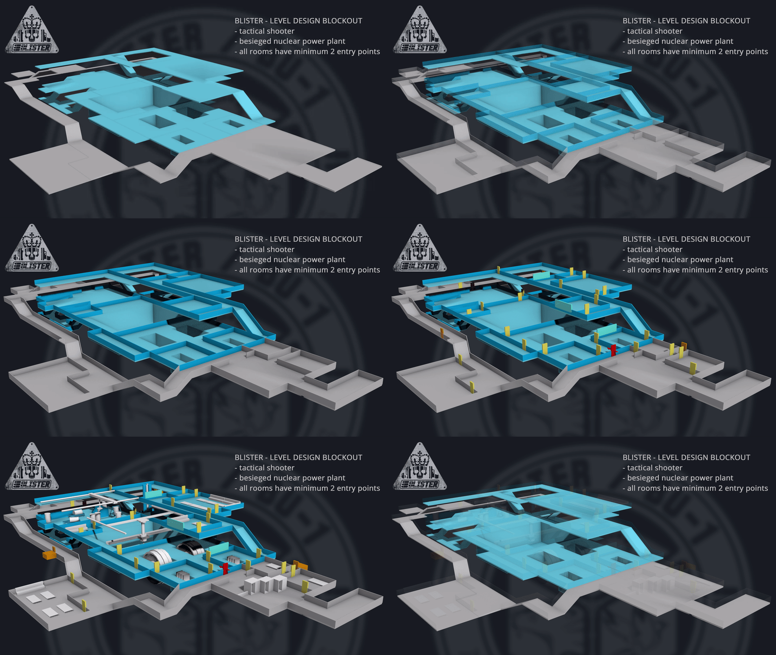
Before I entered UE4 to begin the greyboxing phase I planned out the level on paper and then recreated that plan in 3dsmax. This allowed me to visualise the flow of the level before I began constructing it. Planning it all out properly first meant the greybox phase only took a day to complete.

blister_leveldesign.gif

Before blocking out the level proper I had to set out a sizing standard for all shared properties:

- Walls: 4m height / 20cm depth with a 1m gap for piping, venting and drone access
- Doors: 2m height / 1m width to give AI enough room to manoeuvre
- Drone vents: 50cm height / 1m width to give the player’s drone an Elite Dangerous/letterbox-style opening

Corridor width, window height and so on is variegated, but the minimum allowed corridor size for AI to properly manoeuvre according to a drone plan is at least 2m width. If I wanted, I could build a couple of 1m-width floor-level vent access tunnels that only the player could fit through, either for secrets or gameplay decisions.

I had two considerations while developing both the 3D plan and the greyboxed level: to make each segment of the wing area look and play differently to its neighbour, and to make sure each room in the wing has at least two access points.

The result is an arrangement that a power plant designer might baulk at, but there is a lot of satisfaction in the varied geometry and navigational flow of each room to the next. It might be hard to visualise at the greybox phase but the screenshots below demonstrate the variation in the level design.

A turbine hall

A turbine hall

A pipe flow area

A pipe flow area

A spent fuel pool

A spent fuel pool

A control centre overlooking the waste fuel operation

A control centre overlooking the waste fuel operation

During the greybox phase we tested the placement of doors, cover and obstacles to see what worked and what got in the way of gameplay.

The greybox is finished so now begins the tedious task of whiteboxing--that is, replacing the sparse BSP geometry with actual meshes that represent the final level without having to think about texturing just yet.

Next week’s devblog will probably discuss some changes to our FPS rig and an explanation of how our drone system can save time by loading in previous plans and tweaking them.

Cheers!

Regan & Bret
Item_42

New Website Design!

We've finally got a website worth looking at and it doesn't stop there. Every week we will be writing a devblog post on various aspects of the game, from programming, systems designing and UI development to level design, character art and audio.

I imagine there will also be a lot of posts about weapons because BLISTER is about guns. More guns than you'll ever care to see or play with.

Before I sign off, here's a treat for reading this first blogpost:

BLISTER officers love to party, but someone always gets left out.

- Bret